The 21 Circuit Wiring Harness is a comprehensive solution for automotive electrical systems‚ designed for simplicity and versatility․ It supports various vehicle types‚ from classic cars to race cars‚ offering a user-friendly approach to wiring․ With detailed instructions and color-coded wires‚ it ensures efficient installation and troubleshooting․ This harness is ideal for enthusiasts and professionals seeking a reliable‚ modern wiring system for their projects․
Overview of the 21 Circuit Wiring Harness
The 21 Circuit Wiring Harness is a versatile‚ pre-engineered electrical system designed for automotive applications․ It simplifies wiring for vehicles‚ including classic cars‚ hot rods‚ and race cars․ The harness features 21 individually color-coded circuits‚ ensuring easy identification and organization․ It includes connectors‚ terminals‚ and a fuse block for reliable power distribution․ Detailed instructions and diagrams are provided to guide installation‚ making it accessible for both enthusiasts and professionals․ This system is ideal for modernizing or repairing a vehicle’s electrical system efficiently and safely․
Importance of Proper Wiring in Automotive Systems
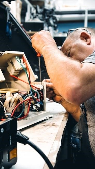
Proper wiring is crucial for the safe and efficient operation of automotive systems․ It ensures reliable power distribution‚ prevents electrical failures‚ and protects components from damage․ Correct wiring practices minimize the risk of short circuits‚ fires‚ and system malfunctions․ A well-organized wiring system also simplifies troubleshooting and maintenance․ For vehicles‚ whether classic or modern‚ proper wiring is essential for performance‚ safety‚ and longevity․ It guarantees that all electrical components function as intended‚ providing peace of mind for drivers and passengers alike․

Components of the 21 Circuit Wiring Harness
The 21 Circuit Wiring Harness includes individual wires with color coding‚ connectors‚ terminals‚ a fuse block‚ and detailed wiring diagrams․ These components ensure efficient power distribution and control․
Individual Wires and Color Coding
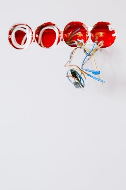
The 21 Circuit Wiring Harness features individual wires‚ each designated for specific circuits; These wires are meticulously color-coded for easy identification during installation and troubleshooting․ The color coding system ensures that users can quickly recognize and connect the correct wires‚ reducing the risk of electrical errors․ Additionally‚ wires are labeled every few inches‚ providing further clarity․ This organized approach simplifies the wiring process‚ making it accessible for both enthusiasts and professionals․ Proper wire management is essential for a clean and reliable installation․

Connectors and Terminals
Connectors and terminals are essential components of the 21 Circuit Wiring Harness‚ ensuring secure and reliable electrical connections․ High-quality connectors are designed to withstand harsh automotive environments‚ while terminals are precisely crimped or soldered to individual wires․ The harness often includes a variety of connectors‚ such as ring terminals‚ spade connectors‚ and butt connectors‚ each serving specific purposes․ Properly securing these connections is critical to avoid electrical issues․ Using heat shrink tubing or electrical tape can provide additional protection against corrosion and abrasion‚ ensuring long-term reliability and safety in the vehicle’s electrical system․
Fuse Block and Circuit Protection
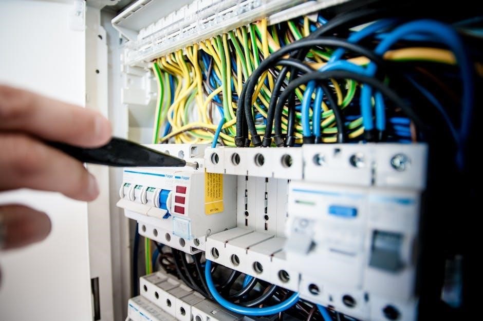
The fuse block is a critical component of the 21 Circuit Wiring Harness‚ serving as the core of electrical circuit protection․ It houses fuses designed to interrupt power supply in case of overcurrent‚ safeguarding the wiring and connected components․ Proper installation ensures that each circuit is protected according to its specific requirements․ The fuse block is typically pre-wired and labeled for simplicity‚ while the wiring diagram provides guidance for organizing wires and identifying fused circuits․ This system prevents electrical fires and component damage‚ ensuring reliable operation of the vehicle’s electrical systems․
Wiring Diagram and Schematics
The wiring diagram and schematics are essential tools for installing and troubleshooting the 21 Circuit Wiring Harness․ These detailed visuals outline the flow of electrical current through each circuit‚ ensuring proper connections and reducing the risk of errors․ The diagram identifies power sources‚ ground points‚ and accessory integrations‚ while color-coding simplifies wire identification․ Schematics also highlight fuse block organization and circuit protection‚ making it easier to diagnose issues and ensure a safe‚ efficient electrical system․
Preparation for Installation
Preparation is key to a successful wiring harness installation․ Organize the harness‚ review diagrams‚ and gather tools․ Ensure a clean workspace for efficient routing and connections․
Planning the Wiring Layout
Planning the wiring layout is crucial for a neat and functional installation․ Begin by reviewing the wiring diagram to understand each circuit’s path․ Identify the vehicle’s electrical components and their locations․ Route wires away from heat sources and moving parts to prevent damage․ Use cable ties and looms to organize the harness‚ ensuring proper routing․ Label wires at intervals for easy identification during installation and future maintenance․ A well-planned layout ensures reliability and simplifies troubleshooting‚ saving time and effort․
Gathering Necessary Tools and Materials
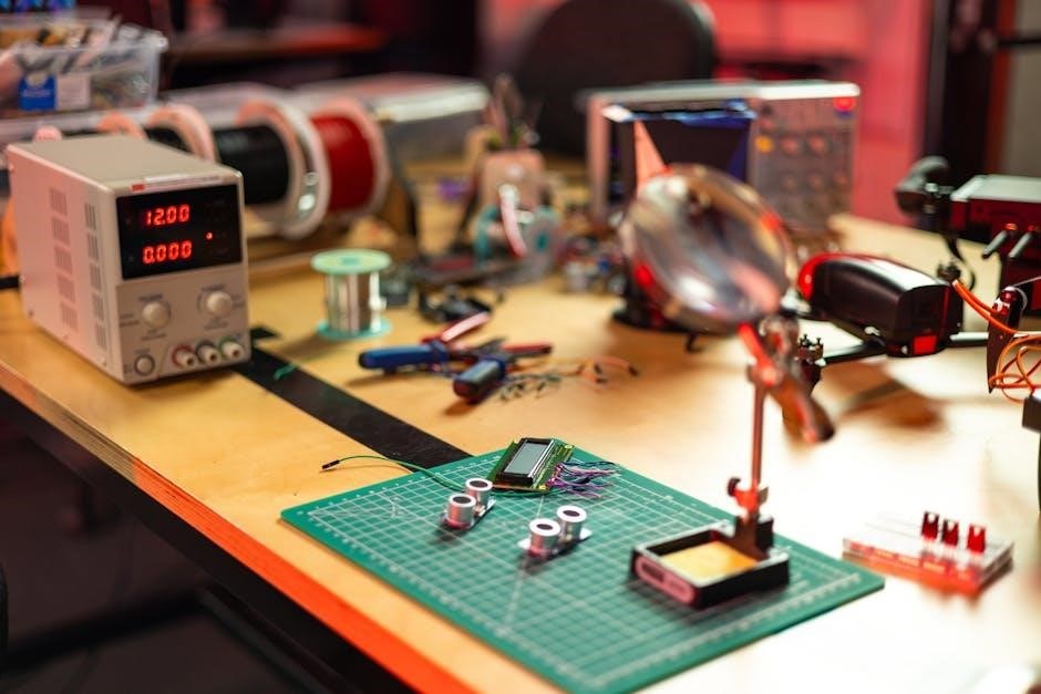
To ensure a smooth installation‚ gather essential tools and materials․ Start with wire cutters‚ strippers‚ and crimpers for preparing connections․ Obtain cable ties and heat shrink tubing for organizing and protecting wires․ A multimeter is crucial for testing circuits and ensuring proper grounding․ Collect connectors‚ terminals‚ and fuses specific to your harness․ Refer to the wiring diagram to identify any additional components needed․ Having all materials ready simplifies the process and prevents delays‚ ensuring a professional and reliable wiring setup․
Understanding the Wiring Diagram
The wiring diagram serves as a blueprint for your 21-circuit harness‚ detailing connections and circuits․ It uses color-coded wires and symbols to represent components‚ ensuring clarity․ Study the diagram to identify power sources‚ ground points‚ and accessory circuits․ This visual guide helps plan the layout and troubleshoot issues․ Familiarize yourself with the legend to interpret symbols accurately․ By understanding the diagram‚ you can efficiently route wires and connect components‚ ensuring a safe and functional electrical system․ Always refer to the manual for specific instructions and safety guidelines․

Installation Steps
Start by organizing wires and connectors‚ ensuring secure connections with proper tools․ Mount the harness neatly‚ avoiding damage․ Connect power and ground carefully‚ verifying all links․ Finally‚ integrate accessories and test each component to ensure functionality and safety․
Mounting the Harness
Begin by laying out the harness in a clean‚ dry workspace․ Unroll and organize the wires‚ using cable ties to manage and route them neatly․ Identify fixed points in the vehicle‚ such as the firewall or frame‚ to secure the harness using clips or adhesive-backed fasteners․ Avoid tight bends or pinching‚ which can damage wires․ Ensure the harness is accessible for future maintenance and that all connections are within reach․ Refer to the wiring diagram to confirm proper routing and secure the harness firmly to prevent movement during operation․

Connecting Power and Ground
Start by identifying the main power wire‚ typically red‚ and connect it to the positive terminal of the battery․ Ensure the connection is secure and insulated․ Next‚ locate the ground wire‚ usually black‚ and attach it to a clean‚ metal surface on the chassis or frame․ Verify that all connections are tight and free from corrosion․ Use the wiring diagram to confirm proper routing and ensure no wires are pinched or damaged․ Test each connection with a multimeter to confirm continuity and proper voltage․ Follow safety guidelines to avoid electrical hazards and ensure reliable system performance․
Integrating Accessories and Components
Begin by connecting each accessory‚ such as lights‚ gauges‚ and electronic components‚ to the designated circuits in the wiring harness․ Use the wiring diagram to identify the correct terminals for each device․ Ensure all connections are secure and properly insulated․ Verify that each accessory operates as intended by testing power and ground connections․ Organize the wires neatly using cable ties or looms to maintain a clean installation․ For high-current devices‚ consider adding inline fuses or relays for added protection․ Double-check all connections to ensure reliability and safety‚ and make adjustments as needed to accommodate specific components or custom configurations․
Troubleshooting Common Issues
Use the wiring diagram to identify and diagnose issues like faulty connections or power supply problems․ Check for loose terminals‚ damaged wires‚ and improper grounding․ Test each circuit to ensure functionality and consult the manual for specific troubleshooting guidance․ Addressing these issues promptly ensures system reliability and prevents further complications․
Identifying and Repairing Faulty Connections
Begin by reviewing the wiring diagram to locate suspected faulty connections․ Visually inspect terminals for corrosion or damage and test for continuity using a multimeter․ Check for loose wires or improper grounding‚ as these are common causes of electrical failure․ If a connection is faulty‚ disconnect and clean or replace the terminal․ Ensure all wires are securely fastened and properly routed to avoid damage․ After repairs‚ test each circuit to confirm functionality․ Addressing issues promptly prevents further complications and ensures reliable system performance․
Using the Wiring Diagram for Diagnosis
A wiring diagram is essential for diagnosing electrical issues in a 21-circuit harness․ Start by tracing circuits systematically‚ using the diagram to identify connections and components․ Check for discrepancies between the diagram and actual wiring․ Use the color-coded keys to verify wire purposes and ensure proper routing․ If a circuit fails‚ isolate the issue by testing each connection point․ Referencing the diagram helps pinpoint faults quickly‚ saving time and reducing frustration․ Always cross-check with the legend to interpret symbols accurately․ This method ensures efficient troubleshooting and precise repairs․

Safety and Best Practices
Ensure proper grounding and follow safety guidelines to prevent electrical hazards․ Use the wiring diagram for accurate connections and consult professionals if unsure․ Always prioritize safety․
Ensuring Proper Grounding
Proper grounding is critical for safe and reliable operation of the 21 circuit wiring harness․ Ground wires‚ often brown or black‚ must be securely connected to the vehicle’s chassis or engine block․ Verify all ground connections are clean and free from corrosion․ Use a multimeter to test continuity between ground points and ensure no voltage drop․ Avoid shared ground points to prevent electrical interference․ Always follow the wiring diagram for correct grounding locations․ Proper grounding ensures optimal performance and prevents potential electrical hazards or system malfunctions․
Following Safety Guidelines
Following safety guidelines is essential when installing a 21 circuit wiring harness․ Always disconnect the battery and ensure the vehicle is in park with the ignition off․ Wear protective eyewear and avoid short circuits․ Use a multimeter to verify wire continuity and check for voltage before connecting components․ Never splice wires without proper insulation‚ and avoid damaged or frayed wires․ Keep the workspace clean and well-lit to minimize accidents․ Refer to the wiring diagram for correct connections and follow all manufacturer recommendations to ensure a safe and reliable installation․